All You Need to Know About V-Groove Glass
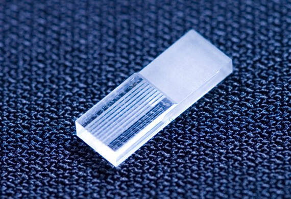
V-groove glass is a precision fiber-alignment substrate with one or more V-shaped channels engineered to locate optical fibers at controlled center positions and pitches.
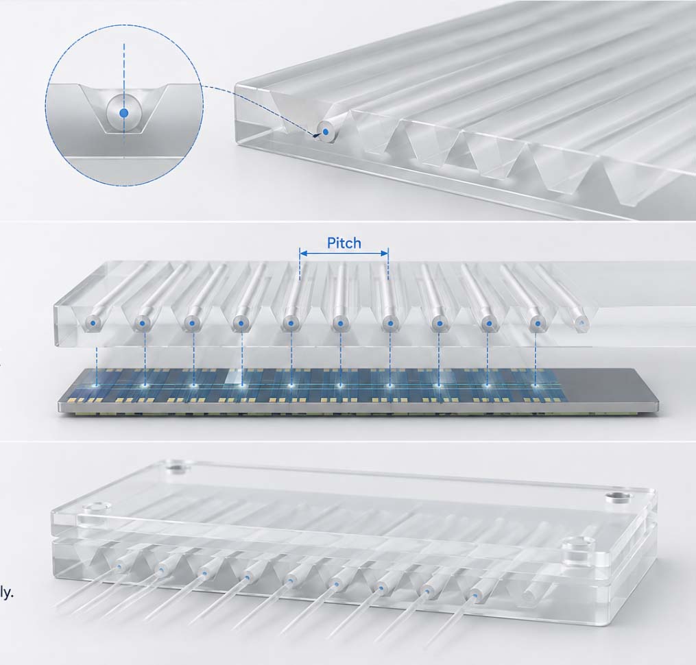
The groove geometry determines the fiber seating position, while tightly controlled groove-to-groove spacing establishes the channel pitch across the array. When combined with a matching cover glass, the substrate forms a compact passive alignment structure for fiber array units, PLC interfaces, AWG devices, photonic chips, and other optical coupling assemblies.
Precision Fiber Alignment
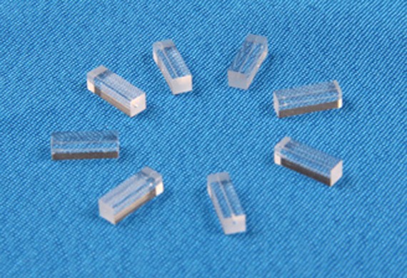
TGVGlass manufactures single-channel and multichannel V-groove substrates in high-purity quartz / fused silica, borosilicate glass, PYREX-type glass, Borofloat 33, and other technical glasses.
Standard and custom configurations can be designed for 50 μm, 80 μm, 125 μm, and 250 μm fibers, with 1, 2, 3, 4, 8, 16, or custom channel counts. Groove pitch, depth, angle, substrate thickness, channel length, fiber center height, and matching cover glass can all be manufactured according to the customer’s fiber-array drawing and assembly requirements.
Custom V-Groove Glass Specifications
| Item | Capability |
|---|---|
| Product | Precision V-Groove Glass / Quartz Substrate |
| Glass Materials | High-purity quartz / fused silica, borosilicate, PYREX-type glass, Tempax, Borofloat 33, and other technical glass |
| Groove Quantity | 1, 2, 3, 4, 8, 16 channels or custom multichannel arrays |
| Fiber Diameter | 50 μm, 80 μm, 125 μm, 250 μm or custom fiber specification |
| Fiber Pitch | 0.127, 0.250, 0.500, 0.750 mm or custom; precision pitch control according to drawing |
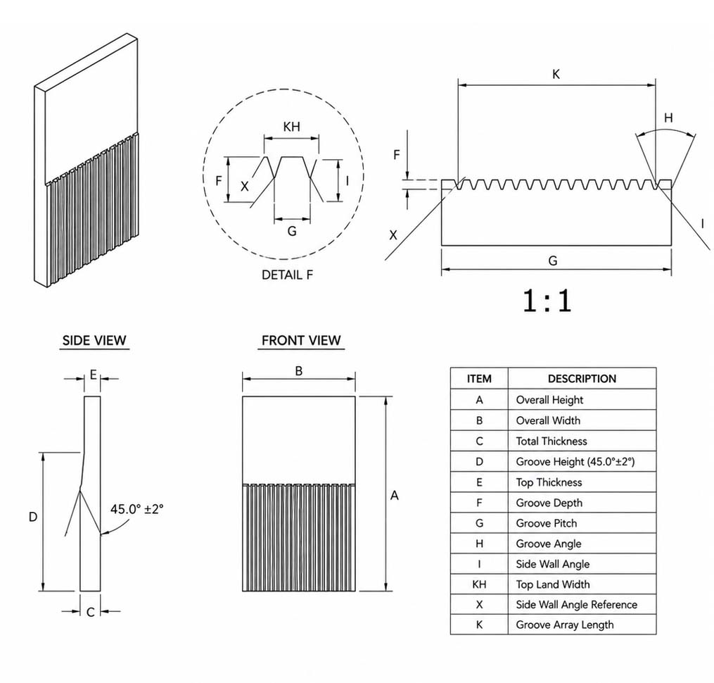
| Groove Geometry | Precision V-groove; typical groove angle 60° ±2° or customized geometry |
| Substrate Dimensions | Custom width and length; typical V-groove lengths of 10 or 12 mm and drawing-based dimensions |
| Substrate Thickness | 0.3, 0.4, 0.5, 0.7, 1.0, 1.5, 2.0 mm or custom |
| Fiber Positioning | Fiber-core positioning tolerance down to ≤±0.5 μm depending on design and inspection requirement |
| Surface Finish | V-groove surface down to Ra ≤0.2 μm; precision-polished substrate surfaces available |
| Cover Glass | Matching cover glass available in standard or custom dimensions |
| Production | Prototype, engineering samples, and repeat batch production |
| Product Option | Groove Layout | Pitch | Cover Glass | Supply Stage |
|---|---|---|---|---|
| 1-Channel V-Groove Substrate | Single fiber | Fiber-specific | Optional | Prototype / Batch |
| 2-Channel V-Groove Substrate | 2-fiber array | Standard / Custom | Optional | Prototype / Batch |
| 3-Channel V-Groove Substrate | 3-fiber array | Standard / Custom | Optional | Prototype / Batch |
| 4-Channel V-Groove Substrate | 4-fiber array | Standard / Custom | Optional | Prototype / Batch |
| 8-Channel V-Groove Substrate | 8-fiber array | 127 / 250 μm or custom | Optional / Included | Prototype / Batch |
| 16-Channel V-Groove Substrate | 16-fiber array | 127 / 250 μm or custom | Optional / Included | Prototype / Batch |
| Custom Fiber Array Substrate | Drawing-based multichannel array | Custom optical pitch | Available | Prototype / Batch |
Need Help?
Send us your fiber-array drawing, fiber diameter, channel count, pitch, substrate dimensions, and cover-glass requirements. We can review the groove geometry and recommend a manufacturable V-groove configuration for your optical assembly.
How V-Groove Fiber Alignment Works
Defined Fiber Position
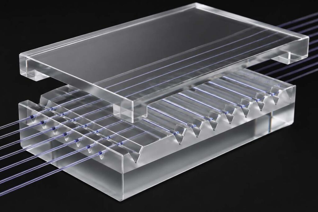
Each optical fiber is supported by the two angled surfaces of the V-groove. By controlling groove angle, depth, surface geometry, and fiber diameter, the fiber center can be positioned at a defined height and lateral location.
Precision groove machining allows fiber-core positioning tolerance down to ≤±0.5 μm for suitable designs, supporting accurate passive alignment between the fiber and the optical interface.
Controlled Array Pitch
The center-to-center spacing between adjacent V-grooves establishes the fiber-array pitch. Standard pitches such as 127 μm, 250 μm, 500 μm, and 750 μm can be produced together with drawing-specific spacing, allowing the fiber array to match PLC chips, AWG devices, photonic integrated circuits, VCSEL arrays, waveguides, and other multichannel optical interfaces.
Cover Glass Retention
A matching precision cover glass can be assembled above the fibers to retain them against the V-groove surfaces and stabilize the completed fiber array. Cover-glass dimensions, material, thickness, and surface finish can be matched to the base substrate and assembly design to support repeatable fiber positioning and reduce mechanical stress within the packaged FAU.
Applications and Benefits
Fiber Array Applications
- Fiber Array Units (FAU)
- AWG arrayed waveguide devices
- PLC planar lightwave circuit coupling
- VOA optical assemblies
- DWDM optical communication modules
- Photonic chip and PIC coupling
- VCSEL and array laser coupling
- Collimated fiber arrays and micro-optics
- Optical transceiver assemblies
- Multichannel waveguide interfaces
Assembly Benefits
Precision V-groove substrates provide passive mechanical alignment without requiring each fiber to be positioned independently during final assembly.
Controlled groove geometry and array pitch help maintain consistent fiber center position across multiple channels, supporting low-loss optical coupling, compact FAU construction, repeatable assembly, and scalable production from single-channel components to high-density multichannel fiber arrays.
Quartz and borosilicate material options also allow the substrate and matching cover plate to be selected according to the optical, thermal, dimensional-stability, and packaging requirements of the finished device.
Why Choose TGVGlass?
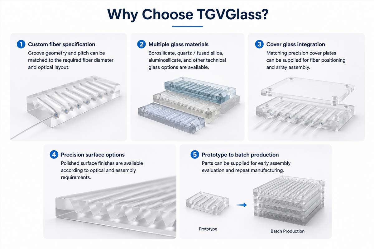
- High-precision fiber positioning: precision V-groove machining supports fiber-core positioning tolerance down to ≤±0.5 μm for suitable designs, with controlled groove angle, depth, and channel spacing.
- Single to multichannel arrays: 1, 2, 3, 4, 8, 16-channel and fully customized V-groove layouts are available for single-fiber and high-density fiber-array assemblies.
- Multiple fiber specifications: substrates can be configured for 50 μm, 80 μm, 125 μm, 250 μm, and customer-specified fiber diameters, with standard or custom center-to-center pitch.
- Multiple glass materials: high-purity quartz / fused silica, borosilicate, PYREX-type glass, Tempax, Borofloat 33, and other technical glass materials can be selected according to optical and packaging requirements.
- Complete substrate and cover-glass supply: precision-polished V-groove bases and matching cover plates can be supplied from prototype evaluation through repeat batch production.
FAQs
Common questions about V-groove pitch, fiber diameter, channel quantity, cover glass, materials, dimensional tolerances, and custom production.
Can the groove pitch be customized?
Yes. Standard fiber-array pitches such as 127 μm, 250 μm, 500 μm, and 750 μm can be produced, and custom center-to-center spacing can be manufactured according to the optical interface or customer drawing.
The same substrate can be designed as a 1, 2, 3, 4, 8, 16-channel or custom multichannel V-groove array.
Can you match a specific fiber diameter?
Yes. V-groove geometry can be designed around the specified fiber diameter and required fiber-center position.
Common configurations include 50 μm, 80 μm, 125 μm, and 250 μm fibers, while other diameters can be evaluated from the customer’s drawing and fiber specification.
Is a matching cover glass available?
Yes. Matching precision cover glass can be supplied together with the V-groove base.
The cover dimensions, thickness, glass material, surface finish, and relationship to the fiber array can be customized according to the FAU or optical coupling assembly.
What information is needed for a quotation?
Please provide the fiber diameter, number of channels, center-to-center pitch, V-groove or fiber-array drawing, substrate length / width / thickness, preferred glass material, cover-glass requirement, surface requirement, dimensional tolerances, and expected quantity.
For optical coupling projects, it is also helpful to provide the target fiber-center height or mating optical component so the groove geometry can be evaluated together with the complete alignment requirement.
Connect with Our Experts
We’re Here to Help
Send us your fiber-array drawing, fiber diameter, channel count, pitch, substrate dimensions, cover-glass requirements, dimensional tolerances, and expected quantity.
Get in Touch
Our team can evaluate the groove geometry and recommend a manufacturable V-groove configuration for your optical assembly.